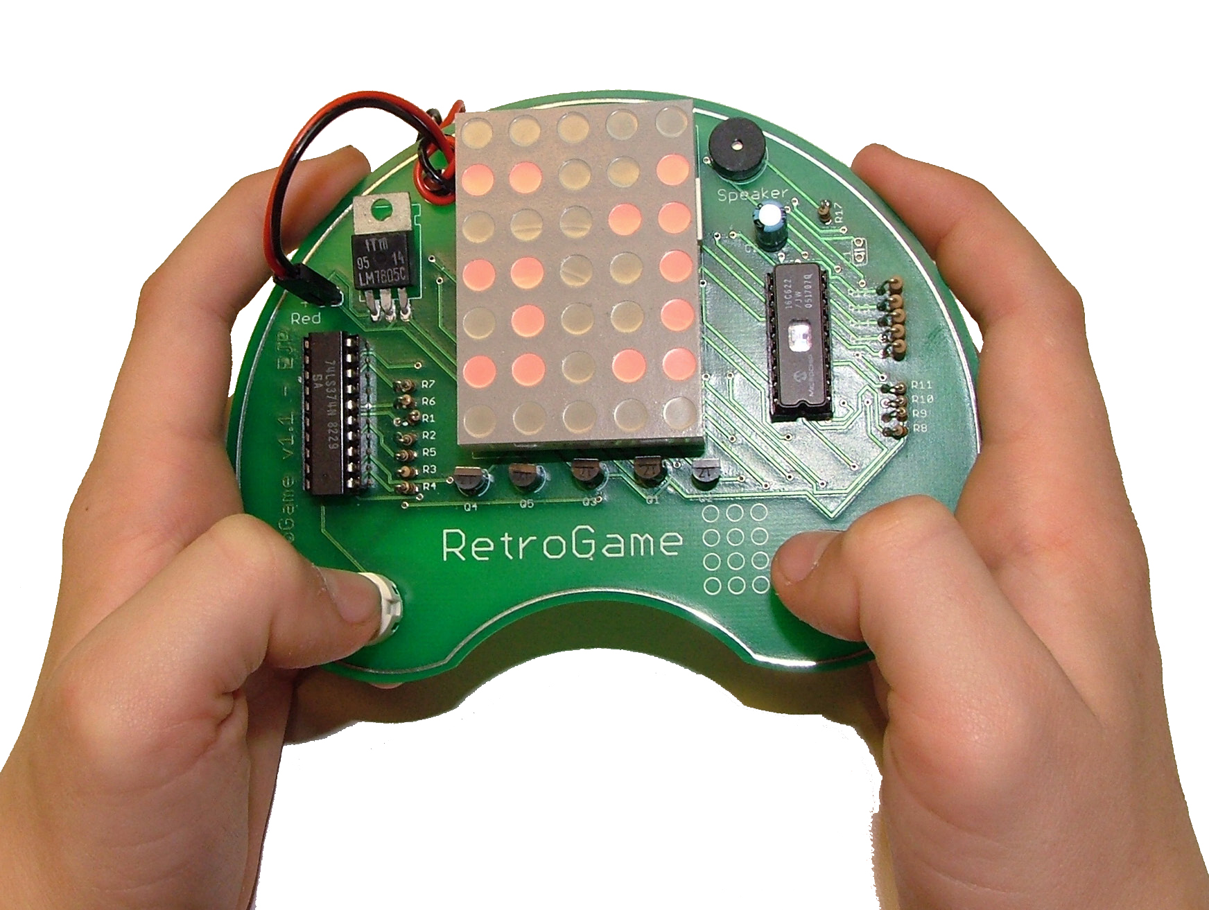
Here's my son playing the game. Click on any of these pictures for
enlarged views.
Close-up of the board with most parts installed.
Note the 7-pin sockets in the middle where the display goes.
This is actually a 14-pin socket cut in half. It is MUCH
cheaper than buying two 7-pin single row sockets!
Here's the same partially stuffed board on edge.
This gives you a good idea of how high the transistors are mounted.
The kids' boards had blue and red sticky dots on both the PCB and
chips. These were meant to help them
both locate where to insert the chips and to orient them
appropriately. This picture is from the PowerPoint
presentation that walked the kids through the assembly.
There's no power switch on the game. To "turn it on" you must
plug-in the power cable from the battery on the back!
The kids often got the polarity wrong. It doesn't destroy
the game when you get it backwards, though the voltage regulator
will heat up and the battery will be sucked dry.
The game uses the PIC's internal oscillator without the capacitor
that you would normally use. This allows the kids to
slow the game down by touching R8. Quite
often the kids accidentally touched a trace on the back
of the PCB with the same effect. Some even learned to do this
strategically when playing the game!